how to test what wire is ring and tip
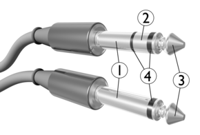
1: Sleeve, ii: Ring, 3: Tip, 4: Insulators
Tip and ring are the names of the two conductors or sides of a telephone line. The terms refer to the telephone plugs used for connecting telephone calls in transmission switchboards. One side of the line is continued to the metal tip of the plug, and the second is continued to a metal ring behind the tip, separated and insulated from the tip past a not-conducting material. When inserted into a jack, the plug's tip usher connects first, followed by the band conductor. In many European countries, tip and ring are referred to every bit the A and B wires.
Neither of the tip and ring conductors is permanently continued to earth ground, but may exist connected to footing during signaling operations. Typically, the band conductor has a directly current (DC) potential of −48V to −52V with respect to the tip conductor when the line is in the on-claw (idle) state. Floating both conductors, not referencing either 1 to basis, minimizes the pickup of hum from whatever nearby alternating electric current (AC) ability wires.
Origin [edit]
The terms tip and band originated in the early days of telephony when telephone operators used plugs to connect customer calls. They are named afterwards the parts of the plug to which the wires were connected. The words are often abbreviated as T and R.
Line voltage [edit]
The telephone company maintains large battery systems that supply DC line voltage for the functioning of analog telephone service at client locations. The voltage supplied is a compromise betwixt operational needs for reliable service and condom precautions for customers and service personnel. The length of the line to a customer telephone interface presents a resistance beyond which the central office voltage experiences a drib and therefore the voltage at the customer site may vary. The nominal bombardment (system) voltage is 52.1 V, based on a 24-cell lead-acid battery.[1] The voltage at a subscriber's network interface is typically 48 5 between the band and tip wires, with tip nigh ground and ring at -48 V.
In the center 20th century, long loops in many rural areas of N America used range extenders, which operated at 100 or 130 volts to ensure reliable signaling. Some rural switching systems were designed to apply range extenders internally and thus share a few extenders among many lines, while for other lines, ane extender was applied externally per line.
To ring the telephone to alert a subscriber to an incoming phone call, the primal office superimposes a twenty Hz AC signal, at a nominal voltage of 105 volts, over the DC voltage present on the idle line.[2] Historically several multi-frequency systems have been used, even so, for selective alerting of multiple subscribers connected to a political party line, for which the A.C. voltage may be every bit high as 150 V.
Polarity [edit]
To provide cathodic protection against corrosion of line wires, the operating potential of telephone lines is typically negative with respect to ground, and the tip side is mostly close to the ground potential. Thus, all power supplies for telecommunication equipment are designated to supply a negative voltage.
In the era of the telephone industry when rotary dial instruments were in use, the polarity when connecting a phone set to the tip and ring wires was usually important only for properly ringing a telephone, especially in political party line service with selective ringing, and for correctly identifying the calling customer on certain party lines for toll calls.
When Touch-Tone service was introduced in the 1960s, the dual-tone multi-frequency signaling (DTMF) tone generator too required right polarity as it depended on the line D.C. voltage for operation. Afterwards Touch-Tone telephones included a diode bridge that eliminated the polarity sensitivity so that consumer phone service is essentially immune to reversal today. However, some special circuits, such as some direct inward dialing (DID) trunks, T-1 lines, and basis start lines connected to field side (concluding) equipment, e.g., a corporate individual branch substitution (PBX) switch, correctly operate but with proper tip and ring polarity.
Color lawmaking [edit]
In on-premises wiring the first or only pair of inside wiring and jacks are color-coded in green for the tip usher, and red for the band side. A 2nd pair is coded in black for tip and yellow for ring. A third pair consists of white tip coding and blue ring coding. For larger cable assemblies more than circuitous schemes, such as the 25-pair color code, are used.
Some telephone technicians used mnemonic phrases, such equally reddish-right-ring-rear, or ring-right-reddish-rough, to remember that the ruddy wire connects to the correct-side post in the wall jack and to the ring on the plug and to the rear lug on main distribution frames. Sometimes rough or ridge was added for jumper wires with a tactile code.[ citation needed ]
References [edit]
- ^ W.D. Reeve, Subscriber Loop Signaling and Transmission Handbook—Analog, IEEE Press (1992), ISBN 0-87942-274-ii, p.138.
- ^ W.D. Reeve, Subscriber Loop Signaling and Manual Handbook—Analog, IEEE Press (1992), ISBN 0-87942-274-ii, p.39.
External links [edit]
- How to Wire a Phone Jack
- Telephony Basic Information and Terms
Source: https://en.wikipedia.org/wiki/Tip_and_ring
0 Response to "how to test what wire is ring and tip"
Post a Comment